Shadow Move Rendering in Killer Instinct: Season 3

A few things have happened lately that have given me the blog itch: I'm stir crazy from the COVID19 pandemic, new consoles are getting announced, a rejected GDC proposal of mine from several years back is fading in relevancy, the Killer Instinct documentary came out, and most importantly there were some interesting Tweets that made me nostalgic.

This really cool effect came to my attention from another tweet that links to some interesting pages by Hugo Elias.

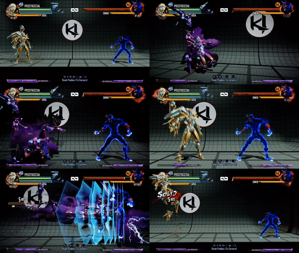
If you are familiar with Killer Instinct on Xbox One, this might remind you of the Shadow Move effects from Season 1+2! And if you know me at all - you might know that I was responsible for maintaining and expanding the renderer for KI when Iron Galaxy became the developer for Seasons 2+3. The first season was developed by Double Helix Games, but they got purchased by Amazon Game Studios at the end of the season, causing Microsoft to have Iron Galaxy come on as a new development partner. I mention all this history because this blog post is going to detail how the Shadow Move effect was revamped for Season 3, but the original effect was developed by engineers+artists at Double Helix and credit goes to them for the great work there. Here is a clip I grabbed from this video of Aria showing off this original effect:

AriaShadowMove.gif

This effect is created almost exactly like the smokey hand shown off by SoerbGames in the tweets. There are two full screen buffers allocated and each frame a simulation step is run that ping pongs between the two in a manner similar to the "feedback" post by Hugo Elias. Each frame, the alpha of each pixel is decreased which causes any color data to fade out over time. However, the warping step is slightly more specific to KI. A reprojection is done to account for camera motion from frame to frame, as this is an in-world effect being simulated in a screen space buffer. In this version I believe this was done with an approximation that avoided a full matrix multiply, but I later changed this to do the full multiply (see this GPU Gems 3 article for details on how to do a reprojection) with the assumption the effect was happening within the plane the characters walk along in the game world. Doing this fixed some issues with drift of the effect that could occur when the camera panned as opposed to the purely translational motion it does most of the time. You can also see in the above clip that there is the inherent limitation that the shadow effect does not persist when off screen do to this being a screenspace simulation. The other primary warping is a 2D flow map texture that is tiled in screenspace used to warp the UV selection after reprojection, which gives the effect its smokey appearance as the texels are distorted over time.

Each frame, the result of the simulation is alpha composited with the scene color buffer after the environment is rendered but before characters are rendered. KI has a pretty hard split between rendering of characters and environments. There are environment particles and UI elements rendered before characters that the shadow moves and characters will then render on top of, and then another round of particle + UI rendering for anything that needs to be rendered in front of the characters. This rigid control is convenient within the constraints of a fighting game where the players are always walking along a fixed plane in the foreground. After the shadow moves composite, characters are rendered on top of them and can optionally inject their color data into the shadow move buffer with an opacity of 1 using MRT. This is done at artist controlled frequencies which you can observe by the strobing nature of Aria's shadow moves when she leaps forward. This lets the effect have a little more time to “breathe” before more color data is injected.

Season 3 Remix

So what about Season 3? We wanted to make a few changes. We did a big overhaul of environment lighting and wanted to make some changes to characters to go along with this. Our art director didn't love the injection of character color directly into the effect - which can add a lot of variability to how the effect looks depending on the color palette and lighting of the character itself. We also wanted some more interesting motion in the flow of the effect as well - optimizations from throughout Season 2 and moving the effect to run in async compute opened up some more budget to do more than a single flow map sample. I joked a few times: "imagine what we could do with *two* texture samples." Here's Aria again with the Season 3 version of the effect taken from this video compilation:

AriaShadowMoveS3.gif

There are a few differences here. Obviously, it's a consistent purple color now, with the character’s materials tinting purple when it is active as well. But if that's all we did, I wouldn't be writing this blog post :) We did want a consistent color across all moves and characters, but we also wanted a more inky and spiraling motion to the effect. Initial attempts to update the motion looked into compositing a large number of octaves of white noise. This produced some interesting effects but ultimately suffered from both being too expensive (too many texture samples to look good) and being too counter-intuitive for the effects artists to tune in any meaningful way. I unfortunately do not have any WIP videos from this period.

These investigations lead me to start looking a new approach that would hopefully be more efficient and easier to tune. I had first heard about "curl noise" when Bill Rockenbeck from Sucker Punch presented their GPU particle architecture at GDC and mentioned curl noise specifically as being a critical element of the look of a lot of their effects. When following up on this, I found this paper, "Curl-Noise for Procedural Fluid Flow," by Robert Bridson et al (who is a bit of an expert in the field of fluid simulation) to be an incredibly easy and compelling read. Bridson's work turns any potential field (e.g. a single channel noise texture) into a 2 channel flow map that results in incompressible flow. This leads to much more believable results at minimal cost.

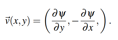
Applying the curl operator to a noise function simply requires the partial derivatives in X and Y at each location. The curl is then simply:

Curl = (Partial Derivative in Y, Negative of Partial Derivative in X)

Curl = (Partial Derivative in Y, Negative of Partial Derivative in X)

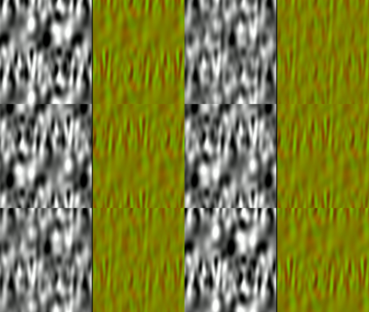
The partial derivatives are just the rate of change in each direction separately. You might be able to derive these from your noise analytically if you can calculate the derivatives for it directly, however I stuck with just computing the finite differences at each texel to allow an arbitrary input texture to be used. My initial version simply used the immediate neighbors, but I did change it to using a “5-point stencil” at the cost of 2 more samples in each direction, which seemed to yield slightly better results at the time. In hindsight, I wish I had spent some more time evaluating the quality of different approaches here and if it really mattered much on the final results. To help visualize what is going on here, here is a tiling simplex noise texture:

SimplexNoiseSmall.png

And here is what happens when you calculate the Curl at each texel using a 5-point stencil:

CurlNoiseSmall.png

This created some really cool effects right away. In fact, an amusing detail in my initial tests of just calculating the curl of an arbitrary input texture that did not correctly tile was that the shadow moves would flow along the hard edge of the texture boundary. This wasn’t what I wanted, but it gave me confidence that the artists would be able to do something cool with it.

One thing that I did need to address still was that the flow was really obviously static. It’s not interesting to see the effect flowing into the same swirls in screen space each frame. There is a really easy solution here explained by Bridson’s paper. The input can be modulated in any way, and the resulting Curl will still be an incompressible flow. This means that the Curl can’t be computed offline, but I only needed to process it for a small texture when relying on tiling noise. For KI, each frame I simply lerp back and forth over time between the noise texture and the same noise texture offset by 0.5 in both U and V. I added support for art to set each texture separately, but the results were good enough that they only needed to adjust the speed at which the lerp occurred.

Shader Toy Example

I’ve put together a shader toy to show this off - and honestly this is the most I’ve ever done with shader toy and I possibly had too much fun with this. I’ve extracted a couple of clips for viewing on the blog without running it, but you can view the whole thing here:

https://www.shadertoy.com/view/Wl2cW1

First, I have an example of a tiling noise texture being generated and a visualization of the flow vectors created from it. The tiling noise is created by mapping UV space to a torus in a 3D noise field - since the torus wraps around in all 4 directions it will tile naturally. We generated the noise textures for Killer Instinct this way in an offline process. As mentioned before, I offset the noise and lerp back and forth between the original and the offset to make the flow more dynamic over time.

NoiseSideBySide.gif

I’ve taken this example of how to calculate the flow and applied it to a one of the green screen videos that is included in shader toy. This ends up being very similar to the original shadow move effect augmented with curl noise (and without any 3D camera reprojection).

ShadowMoveDive.gif

I’ve credited two other shader toys that I cribbed code from for generating the input noise and removing the green screen from the video in the relevant sections. I should mention some interesting ways that the effect can be tuned without modifying the original noise input directly. First, if you multiply the noise values by a constant before computing the curl, it effectively heightens or smooths the slopes in the field, which in turn make the simulation either more or less swirly. If you introduce a multiplier to the flow vectors after they have been calculated, that will instead change how quickly the effect moves through the vector field. Finally, there are controls for how often to inject new data into simulation and how quickly the opacity should decay causing the effect to fade out.

Rendering the Effect

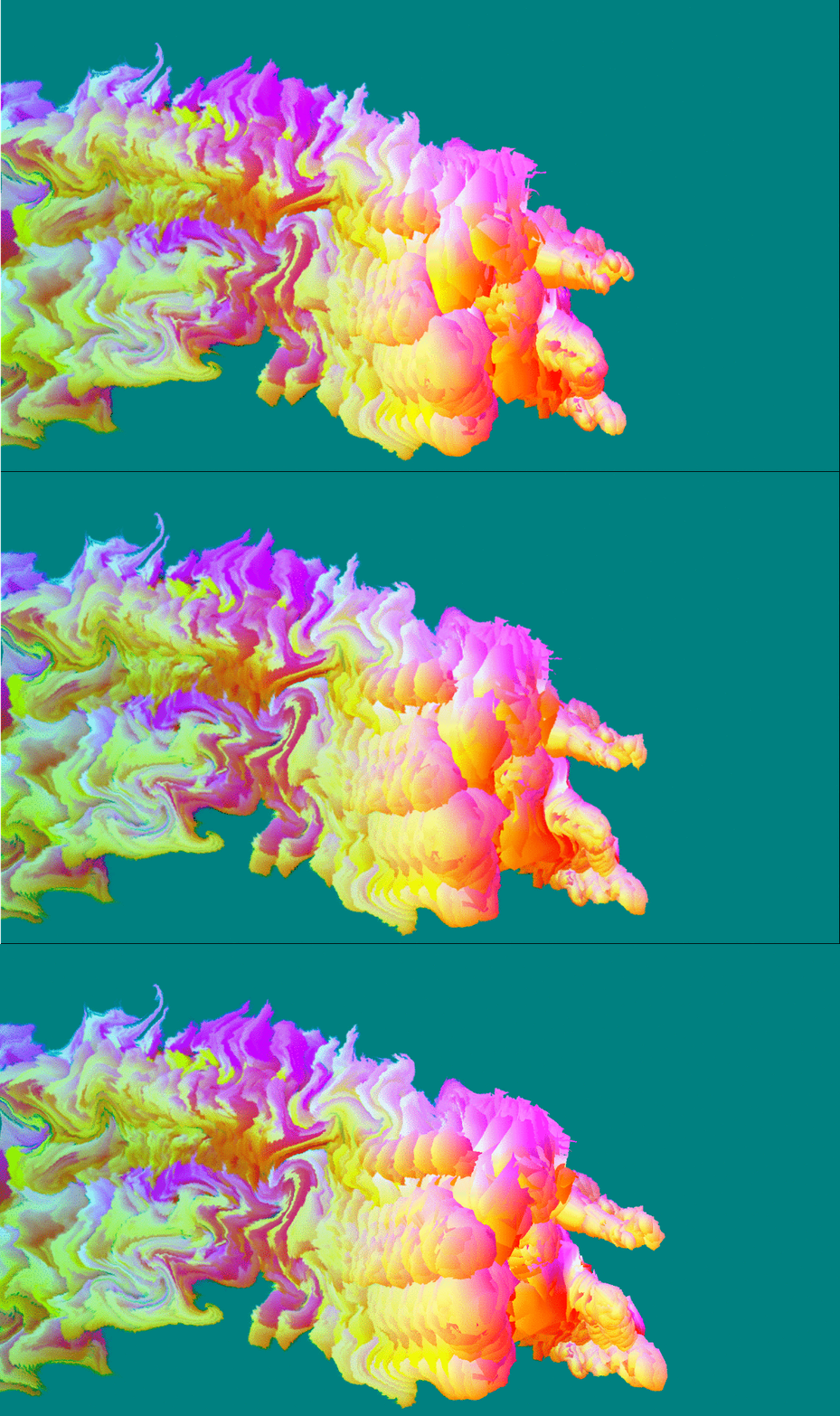
While this yielded some really interesting results right away, there are a number of additional details to creating the aesthetics of the final effect specific to Killer Instinct. First and foremost, because we are no longer using the lit character color as an input of the simulation and want some sort of purple-ish effect, we are no longer tied down to using MRT during character shading to inject the shadow move simulation. Instead, we run a separate character rendering pass on injection frames that render with geometry inflated along the normal vector into what we would call the “blob buffer” because it had blobby characters and creates the main volume of the effect. Inflating the characters gave the effect a lot more volume right away as the effect was running. Here is what the blob buffer looks like simulating for a frame and then just a shot of the character being injected without more warping applied:

BlobBuffer.gif

This buffer has 4 components. The red channel is the age of the texel, which is for most purposes just the opacity, but the effects artists had full control here for how it was interpreted in the apply step, so they can do things like alter the color of the effect over time. As before, this is ticked down with each frame of the simulation.

Age (R)

Age (R)

The green and blue channels hold a distortion vector used to create a refractive effect in parts of the effect. This ended up being very subtle in the end with everything else going on during shadow moves at the same time, but I wasn’t going to fight the artists on using it because it was ultimately cheap to include.

Distortion Vector (GB)

Distortion Vector (GB)

The alpha channel holds what we called “Focus” which is really just a gradient originating from a particular point on the character’s body. This gradient is the important part for deciding the main coloration of the effect. This was hooked up to a color ramp in the apply step that I’ve included immediately after the Focus buffer here.

Focus (A)

Focus (A)

ColorRamp.PNG

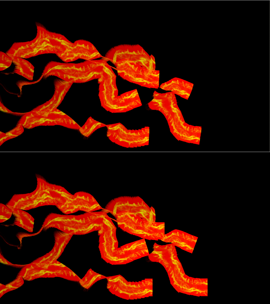
This color ramp is actually 2 ramps stacked together… because the second part of it is used on what we call the “wisp buffer.” The wisp buffer is probably the most logical conclusion to me joking that we could afford two texture samples per pixel instead of just one. To get some more variety and lingering effects, we actually run two shadow move simulations every frame with separate data. This is also pretty subtle, but becomes most obvious when the blob buffer is aging out and the wisps are lingering longer. They also sometimes break off a bit more on their own. The wisps are just screen-space trail renderers attached to key bones of the characters.

Wisp Buffer + Injection

Wisp Buffer + Injection

This is a two channel RG buffer, where the red channel holds an age value just like with the blob buffer, and the green channel holds an opacity value, which comes from a texture provided by art that tiles horizontally. Opacity and age are combined together to determine the blend with the scene color as well as the look-up into the color ramp. We could’ve made this more complicated/flexible with more data, but this is all art really needed for our purposes.

Finally, as mentioned earlier, the effect gets composted into the scene color before the forward lighting render of the characters. Here’s a still of this in action, including a good shot of some refraction happening in the lower half of the effect:

ShadowMoveApply.PNG

Performance

*Rubs temples* If you’ve read this far, you might wonder what time this ran in on Xbox One. I unfortunately don’t have access to a running build of Killer Instinct or any archived PIX captures of the effect as far as I can find and it’s been too many years for me to have specifics. The short answer is “reasonably fast” - Killer Instinct keeps a solid 60 FPS on Xbox One at a resolution of 1600x900, which is also the resolution of the blob and wisp buffers. The flow map update is quite small at just 256x256 pixels. Running synchronously, I believe this took ~0.75 ms total, but don’t take my word for it at this point.

As I mentioned before - I ran it in async compute on top of our prepass because it had minimal data dependencies to current frame data. Killer Instinct uses clustered forward shading, and we had a pretty extensive prepass to minimize overshading during lighting and it resulted in a nice chunk of time to overlap with other work. Furthermore, the first step of updating the the flow vectors didn’t need to wait for the next frame’s camera data to be available so it would get kicked right away on the previous frame to overlap with any inter-frame bubbles when work was not kicked right away from the CPU.

Final Thoughts

Overall, I'm pretty happy with how this turned out. There are some things I’ve wondered about for potential improvements that I never got to at the time. The biggest artifact with the version that shipped is a rippled aliasing whenever really tight swirls occur in the motion. I have a few theories for why this aliasing occurs: my main thought is that there is a limited amount of data being stored in the buffer from frame to frame and as the warping becomes tightly compacted, some data disappears entirely. If we were doing something like simulating a particle system where each particle sampled the vector field to determine its motion, no particles would be lost. As I mentioned before, I also never really got the chance to fully evaluate if my curl vectors were really generated and sampled in the highest quality way from start to finish. Finally, I would point out that I now know a lot more about reprojection diffusion from working on games with temporal anti-aliasing. I bet the legacy version of the effect in particular might have benefited from bicubic filtering, even if diffusion fits with the overall look of a smoky effect.

I hope you enjoyed reading about this! I should credit two of my colleagues from IGS that worked with me on shadow move rendering: Bert Wierenga for early investigations into the Season 3 changes and Rogier Van Etten as the primary effects artist that collaborated with us. Writing this has made me very nostalgic for working on Killer Instinct - I learned a lot from working on that game. Maybe I will feel inspired to find some more time to write-up what else I’ve gotten up to in the past 5 years with computer graphics. If you have thoughts or questions, feel free to leave comments, pester me on Twitter, or e-mail me directly.

#BringBackKI

Improved Spotlight Culling for Clustered Forward Shading

I've been fiddling a lot with tiled and clustered forward shading implementations in my work both professionally and personally. If you're not familiar, there has been some work in the past few years to exploit modern GPU's ability to handle dynamic loops to allow for a larger number of dynamic lights than frequently afforded by a standard forward rendering implementation. Some strategies have been to read back the depth buffer in a compute shader to identify the min/max range of a sub-frustum, frequently referred to as "Forward +" and another set that does not and instead uses fixed partitions in the frustum to identify lights may be touching with regards to scene depth. Really if you're not familiar, there's a good set of links discussing it over on Aras Pranckevičius's blog that will bring you up to speed on a lot of ideas. I'm mostly interested in techniques that do not require reading back depth information, due to the flexibility it offers on scheduling, and you can decide to implement it on either the CPU or GPU depending on what works best for a given project. Emil Persson of Avalanche has a great presentation on their research into that approach, check out the details on his site.

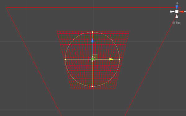
Besides figuring out how to efficiently test lights against a large number of clusters (since more clusters can equate to tighter culling), another huge impact on these techiques is how good the math is for testing a primitive against a given cluster. Persson discusses this at length in his slides, since there are difficulties in testing small clusters against large primitives. The traditional method of testing six planes of a camera frustum against a primitive is ineffective, leaving you with large numbers of false positives. The primitive will tend to look like more of a box than its actual round shape. I've put together a little test bed in Unity just to help me visualize different culling techniques as I've played around with this, and you can see here how badly a point light does when doing six plane/sphere intersection tests for each cluster:

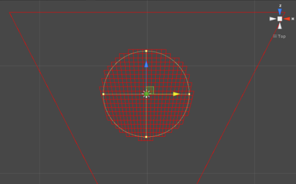
Emil Persson proposed refining the sphere size smaller along each axis direction to get tighter culling. There's also another approach presented by Marc Fauconneau of Intel at Siggraph 2014 and has source code included in their clustered shading sample. The sample is somewhat focused on leveraging Intel's ISPC to compute the culling results, however the math is certainly interesting outside of that context for clustered light culling in general. His approach is to find a plane between the point light and the center of a cluster, and test each point against that plane as what I like to think of as a sort of "poor man's separating axis theorem," in that it would likely be more accurate to test each corner against a newly calculated SAT plane, but that would add a lot more overhead to the test. Here's what the previous point light test looks like changed over to use the Intel approach:

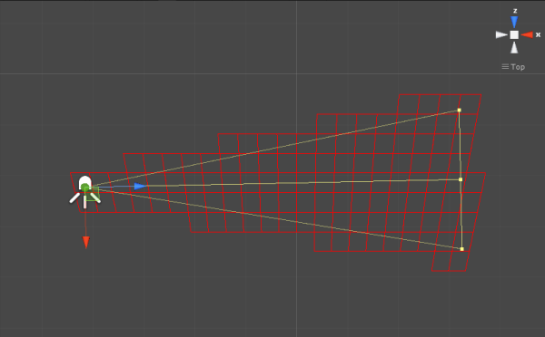
So much better! But as you may have gathered from the title of this post, I'm actually interested in spotlight culling (so I don't have an implementation or results for Persson's approach in this case). For spotlights, Persson states that they approximate the cluster with a bounding sphere and test against that, however his slides are very light on the actual specifics of the math that they use. There's obviously some issues with approximating a cluster with a sphere, especially if they start to become stretched out in depth (the density in the previous screenshots is awfully high to get clusters that are more cube shaped). On the other hand, the Intel approach just leaves spotlights to the reader's imagination, which isn't very useful either. So before I get to how I've gone about filling in the blanks on how the Intel approach might get adapted to handle spotlights, here's a quick screenshot of my own implementation of testing a spotlight using bounding spheres to approximate each cluster:

I have no idea how well my implementation matches Avalanche, and I'm not super familiar with intersection tests for spheres and cones, but my rough logic is as follows: start with two simple tests of sphere/sphere with the spotlight position+radius against the cluster sphere (early out with failure) and a point/sphere test against the sphere using the origin of the point light (early out with success if this passes). Then for the actually interesting bit, I find the "maximum angle" that would cause the sphere to intersect the cone by taking the arcsine of the sphere radius over the distance between the spotlight origin and the sphere center. I sum the resulting angle with the angle of the spotlight (or half of the angle in my sample code since the "angle" in unity is for the full spotlight width, i.e. think radius vs. diameter). This gives me an angle I can test against with the dot product of the spotlight direction. I suspect I'm struggling to describe this super clearly, so here's the source code for my test function in C#/Unity:

I'm not super jazzed that my spotlight code includes trig and inverse trig functions, and the nagging feeling that someone much smarter than me probably has a much better way of doing that test. So it's not what I would necessarily refer to as "production ready," but it does do a good job of approximating the conical shape of the spotlight! Fellow Iron Galaxy'er Nate Mefford made the useful observation that there's likely cheaper approximations of the ASin that can be used, and of the trig in general. Possibly one strategy would be to use a rough approximation as an initial early out and then refine with the full arcsine for the tightest level of culling.

On a similar note, I would also call out that theoretically the set of clusters has already been reduced at this point, especially if the code executing on the CPU where that sort of thing is easier to architect. In the code given, you start by rejecting based off of the full sphere first, and then worry about the more expensive bits. If I'm reading the slides from Persson correctly they sweep across their clusters with fasts tests against the planes of the clusters in each major axis of the view frustum (i.e. left to right, top to bottom) to find the boxy-looking culling as shown with the point light at the top of the post, and only *the* do the more expensive culling on the reduced set, which may only be doing 10% of your total cluster count. In my experience doing something like that is a lot harder in a compute shader, where I've found throwing a separate thread at each cluster to work well. Almost so well I'd use the phrase "embarrassingly parallel" but then you'd have to put me down out back for using buzzwords, but the idea is that all clusters are totally independent of each other and are just reading from a shared buffer of total lights to cull. I think possibly the approach to get some hierarchical culling on the GPU would be to do a small amount of coarse culling on the CPU. For example: split the frustum into 8 octants, build light lists for each octant, and then dispatch separate compute jobs for each one.

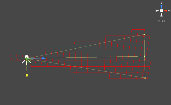
I'm much happier with how my approach to adapting Intel's point light test to handle spotlights has turned out as far as the raw math goes. I drew inspiration for the idea from Christer Ericson's description of testing a cone against a plane in Real-Time Collision Detection, where he uses a couple of cross products to figure out the vector on the cones cap that points towards the plane. My idea was this: start by testing the spotlight a full sphere, then orient a plane on the side of the cone and repeat the test against that plane. That oriented plane will have the vector from the spotlight position to the closest point on the cap as one of it's tangents, and the second tangent (and then the normal), can be found with the cross product of that tangent and the vector from the spotlight position to the cluster center. Here's the result of my test with the spotlight from before:

I chose this spot in particular because there's some clusters misbehaving behind the origin of the spotlight, which could be improved upon by testing yet another plane oriented with the spotlight itself (a hemisphere shape would result if you combined that with just the initial pointlight test), but I haven't decided if practice that's actually worth doing. In the given example, only 2 additional clusters would be culled. Furthermore, the previous test resulted in 588 clusters being lit, this test results in 506. There's already an improvement over the sphere approximation in this example, so it's not like we need to play catch-up by throwing even more math at the problem. The code is a bit longer than the previous, but at least avoids anything more expensive than the cross products. Here's my source code for that function, I should note that I use Fauconneau's optimized code for testing the vertices against the plane:

In conclusion, I wanted to give a little discussion on culling spot lights against clusters along with some code samples, since it seems to be a bit glossed over in some of the resources floating around out there, but the resources *are* excellent, so definitely go read those if you are not familiar with the work in culling lights with frustum clusters. Personally, I like the projected plane approach because it's very clean to have the math for the spotlights built directly out of the point light culling logic, and in my particular implementation, I'm currently seeing the best quality results with it. As I said before though, I'm not confident that I have the best approach to doing a sphere/cone test, especially with regards to performance.

Finally, I leave you with one final shot that I didn't find a reason to include earlier, of how poorly the results are by using the cone/plane math from Real-Time Collision Detection to test against six plane similar to the point light shown at the beginning, clocking in at 1408 lit clusters, for a further reminder that testing against the six planes of the cluster frustum is usually a bad idea:

Thoughts on Engine Licensing

I seem to have hit a strange impasse of decisions regarding game engine licensing. It used to be a simple decision on my part for licensing an engine for personal use: cobble together the cheapest Unity license possible. Now things have changed, both personally and with modern game engine licenses. Its led me to be thinking about this a fair bit recently and I decided maybe I should just write it up as food for thought for anyone that might stumble across this.

Background

I learned Unity extensively at my first game development job Michigan State University back in 2008. The head of my lab had decided to begin using the engine both in the classes he taught and in most of his academic classes, accurately predicting that its trajectory would lead it to be an affordable and beginner-friendly tool for game development, that would still have enough depth to produce a top tier game if put in the right hands.

The university had previously used the Torque engine for teaching 3d game design classes, which gave full access to native source code... but apparently the view on that was that it was more a necessity than a bonus to be able to get around stability issues when using the engine. Unity on the other hand has resisted allowing full source access from the beginning. This always seemed to make sense to me since their business model has seemed to roughly be to market a fully capable 3d game engine as a piece of software akin to Photoshop. The parallels can definitely be drawn to Flash's use as a 2d game engine, which at the time seemed to be filling a vacuum of products with real consumer demand, Flash seemed to me to be a piece of software intended more for generic "interactive media" but was instead being coerced into being a fully functional architecture for increasingly ambitious 2d games. It always struck me as incredible that something as simple as adding a data structure equivalent to the STL's vector would be considered a groundbreaking advancement in Flash game performance optimizations. But, enough about Flash, my point is that I'm happy I hopped onto the Unity train when I did. It's proven to be an effective tool for prototyping new ideas, rapidly building projects in game jams, testing out some of the latest rendering techniques, and building full scale projects intended to have hours of gameplay.

GDC 2014

As you may be aware, this year's GDC brought in a whole wave of competitive moves by several of the larger game engines. Unity announced the next major iteration of their engine and key features in development for it. My rapidly expiring educational license is in limbo due to a crashed hard drive. Now the desire to go through the hassle of trying to recover it is rapidly fading since a new engine version would require a new license anyways.

I'm nearly at the end of ways I can weasel my way through pro trials, all my academic licenses from my days at University are either for much older engine versions or have expired. Unity's previous introduction of a 99 dollar educational use only license was a great stab at what I'm going to talk about when I get around to actually making a relevant point in this post, but that license is now very difficult for me to acquire as my ties to the University dry up. Unity offers a 75 dollar a month subscription license, but witha 12 month contract, it doesn't really save anyone any money. If you only need Unity for 3 months, you're still going to end up paying the full prices.

In the mean time, Crytek and Unreal both announced competitive pricing for their engines at GDC. Crytek offers a 10 dollar a month subsctiption service now. My understanding is that this allows access to a gameplay layer of sorts for licensees, but a full engine source license is different. Unreal on the other hand stepped forward with a 20 dollar a month subscription with full access to the engine source for Unreal Engine 4, a step away from the restricted model they followed with UDK for Unreal Engine 3. This comes witht the caveat that you must pay 5% of your revenue to Unreal if you release a commercial game.

This fascinates me. Unreal has single handedly made itself a very interesting engine for people like me: people that have little to no intention of releasing a commercial video game.

Non-Commercial Use

 My continual usage of Unity in my spare time is driven by a few key pillars:

  • Staying familiar with an engine I have expert level knowledge of is worthwhile, even though Iron Galaxy historically uses Unity very rarely. If that were to change, which is possible since we do lots of external contracting, my experience would certainly come in handy. It would also likely be useful in the unlikely case of Iron Galaxy being sucked into a dimensional rift while I'm oversleeping and suddenly I find myself in need of a new job.
  • Unity makes for an excellent choice for experimental game design: whether its a game jam or a prototype of an idea that might eventually turn into a real thing, fast set-up and fast iteration make it very appealing engine for that sort of thing. The free version does a very decent job of this still. I've been using free version features only to slowly poke at a prototype of a silly Manatee-based game. I might release it at some point. Probably for free. Probably no one will notice. That's fine.
  • It offers an interesting trade-off as a choice for prototyping rendering techniques. On the upside, boring things like particle systems and model importing are handled for you already. On the downside, you have to work around the choices made by the rendering engineers there. This is true of all licensed engines. With full source this becomes easier, but only to the extent that merging the latest engine revision might be a huge headache if you get too agressive with modifications. It's best to live in harmony with an engine instead of fighting it, and I think its worth practicing that in projects outside of the office.
  • Students, indies, and professionals might find implementations and blogs about work in Unity interesting since they might be using it too.

So here's the dilemma: I could license Unity 5 and go on my merry way. Or. I could purchase a new guitar with that money. What I have done is license Unreal 4 for 20 dollars, and I don't have to pay for a full 12 months if I don't see the need to. Unreal has out of the blue become something very interesting to me for use as my platform for prototyping new techniques. In fact, Unreal has done a huge favor to researchers everywhere that might want to prove out their ideas in a commercial engine. With full source access, building in even esoteric (if potentially ill-advised) revisions to the engine should be painless. They can keep their source drop even if they don't keep paying for source access, and they can share it freely among their groups/labs/grad student slave labor/etc. I'm excited to be able to tell a researcher that there's no reason they can't test something out in a commercial engine.

There's some problems with jumping ship from Unity for the time being though:

  • I like leaving the door open to using cutting edge or impractical rendering tricks in small projects where the render budget might otherwise go unused.
  • My accrued Unity knowledge will begin to collect more dust than I'd like.
  • Iron Galaxy already has a lot of familiarity with Unreal, including myself. So I lose the benefit I mentioned before about diversifying my experiences.

Why Any of this might be relevant to Unity

There are two reasons why I think Unity is leaving themselves exposed in a few ways to Unreal's decisions besides the competitive pricing they're offering. There's the aforementioned issue of the ease of access for academics to use it as a test bed of choice. Furthermore, Unreal is introducing a marketplace for selling engine enhancements, just like Unity does. It seems that the Unity Asset Store has been very successful for them: it allows additional engine features that they have not personally developed, and they get a cut of the revenue of transactions in the store.

In my mind, developers targeting tools development are essentially paying for the engine twice. Once for the license, and again with a revenue cut. Unreal's making a compelling point that for that system to make sense: the up front cost should be as low as possible.

Where this leaves Me

I think 1,500 dollars for a game engine is incredibly cheap for developing a commercial game. I'm less inclined to think it makes sense for somebody making an art game or prototyping a new rendering technique, or even just someone making improvements that Unity or Unreal is getting a cut of in their stores when other developers by their tools. So for now it seem increasingly likely that I'll be splitting my free time between Unity and Unreal. Not sure if I have the appetite to give CryEngine a spin just yet. In the end, it surprises me that I'm even having to have this dilemma, since Unreal and Unity used to occupy very different spaces when it came to hobbyists. Weird.

Notes on Skin Shading

If you've followed my musings for a while, you'll know that I real-time skin shading is one of my favorite topics to read about, regardless of what I'm actually working on professionally. It's been a while since I've posted on the subject which is a bit remiss since there's a useful note on Pre-Integrated Skin Shading that I believe I've neglected to post here (I skimmed through my history and couldn't see anything about even though I know I had the intent to), and a few useful presentations have discussed techniques in the past year or two that I've never mentioned here. For reference, a younger version of myself has written very mediocre posts on the topic here and here. I figure I ought to continue that trend.

First and foremost, in response to my original post about implementing Pre-Integrated Skin Shading (PISS) into Unity3d, David Neubelt from Ready at Dawn (and I saw it on the comments at least somewhere where that post got reposted) pointed out a minor bit of incorrect math in the generation of the look-up texture. If you the examine the math in Penner's slides, you'll see the following figure:

$ D(\theta) = \dfrac { \int_{-\pi}^{\pi} \cos (\theta + x) \cdot R(2 \sin (x / 2))\,dx } { \int_{-\pi}^{\pi} R(2 \sin (x / 2))\,dx } $

What's of interest here is the limits of the integral. If you go and look at my Unity code in my old post about PISS, you might notice in the sample code that I use $-\pi \over 2$ to $\pi \over 2$ for the integral's loop. This is an error that I carried over from Penner's sample code in GPU Pro 2. When corrected to $-\pi$ to $\pi$ to match the integrals in the equations, there are only subtle changes, but those subtle changes are for free at run-time from improving the look-up texture quality, so there's no reason not to have them.

Speaking of David from Ready at Dawn, him and Matt Pettineo have included their experiences with using PISS in the upcoming title The Order: 1866 in their presentations at SIGGRAPH and GDC. They include useful math for combining PISS with Spherical Harmonic lighting. In fact, all of the sets of course notes from the Physically Based Shading course at SIGGRAPH are worth looking at if you haven't already.

Finally, I saw John Hable's talk at GDC this year about his experiences with trying to produce high quality, compressed facial animation. The interesting bit about his presentation is that he touches briefly about skin rendering towards the end. He has an interesting approach on shading that goes back to Texture Space Diffusion, which is what most modern techniques have used as a reference for a high quality result but have tried to get away from for more performant options. The key bit to Hable's approach is that instead of doing multiple convolutions, he does a one-pass approximation in a 256x256 texture. It seems like this might have some advantages in certain contexts over PISS or screen-space techniques, but obviously it suffers from the inevitable scaling issues of needing to process a separate texture for each character visible on screen at the same time.

Scaling a Sobel Filter

I've worked on a few different games that use edge detection to render non-photrealistic lines and this has lead me to do a fair bit of fiddling on my own time with various techniques, looking into both the quality of the effects and how to optimize them. This post is about my experiences taking one of the simplest filters in use and looking for a way to make it even cheaper without drastic quality loss.

An interesting issue with post-processing in any game, is that if you take it to a new platform that is substantially less powerful, how to scale the quality of it without requiring re-tuning of content (i.e. you don't want art to have to go through and readjust every use of depth of field in the game because your original technique was too complicated). Morgan McGuire discussed the importance of this in his methods for scalable motion blur and depth of field processing presented at Siggraph 2012 (http://graphics.cs.williams.edu/papers/VVSIGGRAPH12/). While McGuire's talk is focused on scaling between console generations, the engineers over at Unity frequently have discussed porting expensive effects down to mobile which is a similar problem (http://aras-p.info/texts/files/FastMobileShaders_siggraph2011.pdf, http://aras-p.info/blog/2011/02/01/ios-shader-tricks-or-its-2001-all-over-again/). In an ideal world, you can mitigate these situations by planning for your slowest platform from the beginning, but the realities of the games business don't always allow for that sort of planning.

One of the most straightforward and efficient ways to render lines for a non-photorealistic render in real-time is to process a sobel filter as a post-process on some property of your main render, typically depth and/or normals. The way a sobel filter works is pretty simple, here's a quick refresher (adapted from the wikipedia entry). For a source image\(\matrix A\), two convolution operations are applied:

$$ \matrix {G}_x = \begin{bmatrix} -1 & 0 & 1 \\ -2 & 0 & 2 \\ -1 & 0 & 1 \\ \end{bmatrix} * \matrix A \\ \\ \matrix {G}_y = \begin{bmatrix} 1 & 2 & 1 \\ 0 & 0 & 0 \\ -1 & -2 & -1 \\ \end{bmatrix} * \matrix A $$

The best way to think about these are applied in an implementation is that for the processing of each fragment, the values in the matrix notation are simply weights applied to the surrounding pixels sampled by the program, and then summed together. The magnitude of the gradient approximation from the sobel filter can be calculated via \(\sqrt {{{G}_x}^2 + {{G}_y}^2}\). That magnitude is typically then used to determine if the fragment should be a line or not.

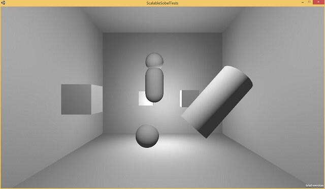
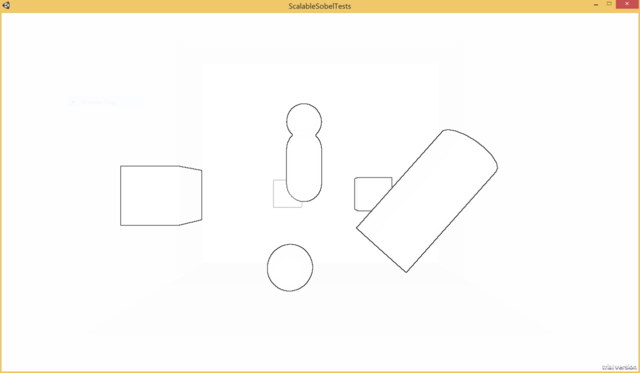
Here's a shot of a test scene I've set-up in Unity to run my effects on:

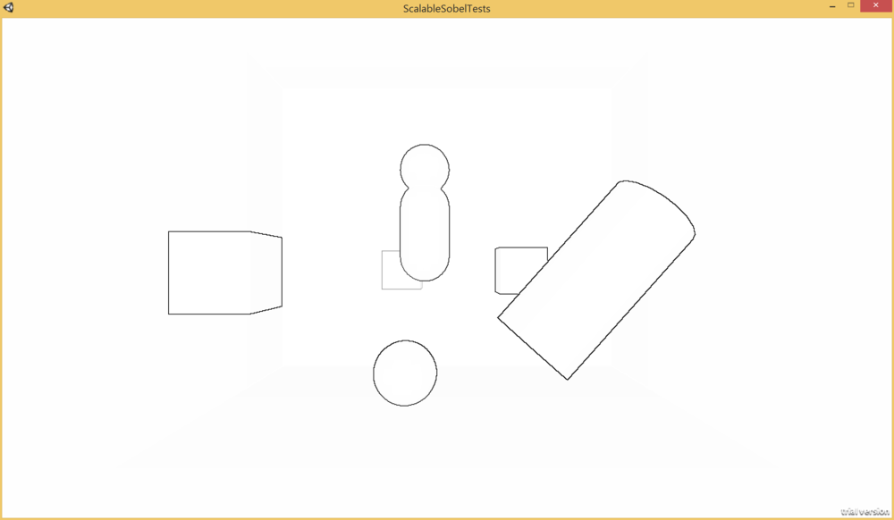
I've taken the built-in edge detect effect that ships with Unity pro has a couple of filtering variations. I've simplified the "SobelDepthThin" filter a bit (it's "thin" since the filter is tweaked to exclude exterior edges, which gives the nice property of avoiding artifacts with other depth based post processing). I've tweaked their implementation slightly to more closely match the standard Sobel filter formula I discussed previously. Here's a shot of a test scene using the effect, rendered as one minus the gradient magnitude, blended against white instead of the scene color so that only the edges are visible:

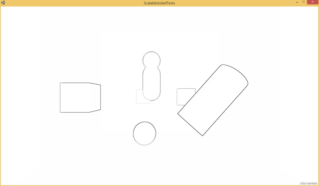
So here's a thought, what if we removed half of the weights out of the image? At some point there's only so much you can optimize the ALU of a relatively simple shader taking 9 samples (the 9th is the center pixel) to get any benefit, dropping 4 samples would have a benefit no matter what. Here's what it looks like if the vertical and horizontal samples are simply commented out of the shader:
 

This is a bit interesting since the main details of the effect are mostly intact, but the lines are rendering more faintly for details across smaller depth discontinuities, such as with the bottom left of the capsule in the center where it overlaps the box. It seems like there should be a way to account for this and have the effects line-up reasonably well. What I realized with this was that there's actually a super convenient approximation that make these have very similar properties without hand tuning any parameters. Let's step back and look at the math for calculating \(G_x\) and \(G_y\) from the following set of samples \(M\), where \(x\) is the center depth sample:

$$ \matrix {M} = \begin{bmatrix} a & b & c \\ d & x & e \\ f & g & h \\ \end{bmatrix} \\ \\ {G}_x = -1 * a + 1 * c + -2 * d + 2 * e + -1 * f + 1 * h \\ \\ {G}_y = 1 * a + 2 * b + 1 * c + -1 * f + -2 * g + -1 * h $$

I wrote out all of the multiplications to try to help illustrate how they match up to the kernels up at the beginning of the post. In the initial approach of just dropping the weights effectively turns samples \(b\),\(d\),\(e\), and \(g\) into zeros. The trick to balance how the filter is behaving, is to treat each of those terms as the average of the two neighboring samples. Here's what that would look like plugged into the equations:

$$ {G}_x = -a + c + -2 * (0.5 * a + 0.5 * f) + 2 * (0.5 * c + 0.5 * h) + -f + h \\ \\ {G}_y = a + 2 * (0.5 * a + 0.5 * c) + c + -f + -2 * (0.5 * f + 0.5 * 0.h) + -h $$

And then if we combine the terms together, we get something very clean:

$$ {G}_x = -2a + 2c + -2f + 2h \\ \\ {G}_y = 2a + 2c + -2f + -2h $$

So the moral here, is that I just used a bunch of math to simply express "multiply the diagonal weights by 2." I guess it was really just an excuse to add more LaTeX to this post. What's more interesting is seeing how this holds up in an actual scene.

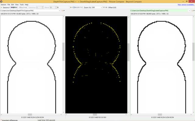
This actually looks very close to the original image! Close enough that the differences are what you call subtle. Clearly, there have to be differences Here's a BeyondCompare diff of a close-up of the cylinder/sphere intersection in the middle:

The original version is on the left, the simplified version on the right. As you can see, there are actually differences being picked up, but if you look closely a lot of the details missing are the grey / semi-opaque pixels from the left are completely black on the right. So, unfortunately, there is some quality to be lost, but nothing is for free. If you're doing something like running FXAA afterwards, that would probably more than compensate for the loss of those minor details, although on something super low powered like a mobile platform that's probably not an option. Perhaps the coolest thing that I like about the trick though is that straight lines like the vertical ones on the capsule end up essentially correct under the approximation.

So in summary, dropping half the weights out of a sobel filter turns out to potentially not be the worst idea in the world. Additionally, this post was the first time I've use LaTeX or any sort of fancy styling for it, so hopefully MathJax did not steer me in the wrong direction with its claims of "works in all browsers." Hopefully I'll get around to writing some more technical pieces in the not so distant future.